Commentary on design " 20-20
"
Notes were added as alternate ways developed.
I call this design "the "20-20" because I thought the average sailor could build it in twenty hours, for about $20, and it would weigh in at about twenty pounds. It looks more complicated than it really is. The dimensions are not critical and the materials specified are only suggestions.
As of May 2001 I was forced to admit this was not the case from feed back of several builders.
Based on this feed back. $30.00 US is
possible but the man hours are higher by most reports.
However even at 40 hours it is not a big project.The skills required are not much greater than those needed to build a birdhouse. No welding or machine shop work will be needed and if necessary it could be built with hand tools.
This is one to prove my point.
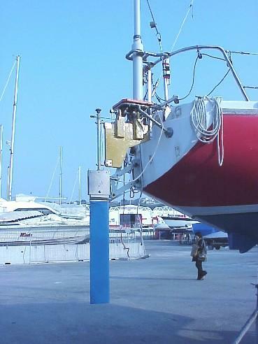
The "Birdhouse" is one builders interpretation and it is lashed to the boat without any new holes. The PVC oar carrier proved quite strong enough for this 29 foot boat in twenty knot winds.My purpose in this design was to provide a simple, low cost way to evaluate the advantages of wind vane self-steering on small boats. It is not intended to be long lasting nor a particularly strong device. I have designed and built several versions and used them on my own small boat along the West coast of Florida and on one single-handed trip over to the Abacos. This simplified version uses the same basic geometry. Trial sails on my current ocean ( an inland lake ) indicate that the simple design works just fine.
Many builders agree that the intent has been met.
I hope you will find it so.

After using this gear you should be in a much better position to evaluate self-steering on your boat and decide if you need to buy one of the fine commercial models. This experience could also convince someone with the right skills and tools to build one using good sea going materials and know how it would work before spending very much on stainless or bronze.
I propose that you mount the gear for testing with temporary blocks bonded to the transom with something like 3M's 5200 that will allow you to remove them without damage to the gel coat once you have finished evaluating the device. This material will adhere well enough to lift gel coat if brute force is used to lift the blocks. Cut the blocks and then cut the bond with a knife as a little force is applied.
Existing hard points such as the backstay tang or an outboard motor mount might fit in your mounting scheme.
The following comments on the drawing sheets are intended to serve as drawing notes due to the limitations of having to fit these drawings to letter size sheets. Most users will not likely have access to Cad plotters and such. I will also try to add some comments about the actual fabrication techniques that I have found helpful. E-mail me if you need clarification.
waltmur@mindspring.com
Note: The dimensions shown on most of these
drawings are to two places. This is due to the round-off settings of the CAD program I used and does not in anyway reflect the need to work to such tolerances.Also, I have used several outdated photos and many alternate ways of building many of the parts. These are intended to present ideas and not be rigid requirements. Feel free to " Mix and Match ".
The most important comment I can make is to say that keeping
the friction in the vane support and linkage low is going to make
a better device. Make sure the joints are free and non binding
but without excessive free play or back lash.
See the "JPG Drawings" page for the over all view and individual drawings with links to the related photographs.
These drawings in JPG format show enough detail and dimensions to be used as is for building. I emphasize that they are only suggestions and any could be changed to fit your boat.
The geometry of the linkage action is the critical thing. The relations of the different shaft axes and crank arm lengths
should be close to the ones shown.1 - Vane Click on thumbnails to enlarge the view
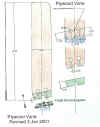
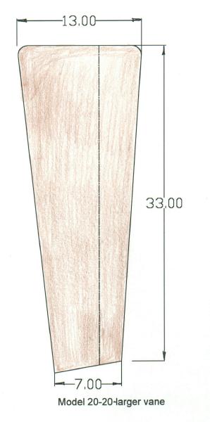
Larger vane
See photographs on "More Photos" page for a series of layout and assembly photos of a vane being built with plywood. Any stiff light
material will be fine for the vane. I have found Douglas fir plywood with the edges sanded to a flat airfoil shape to work well.
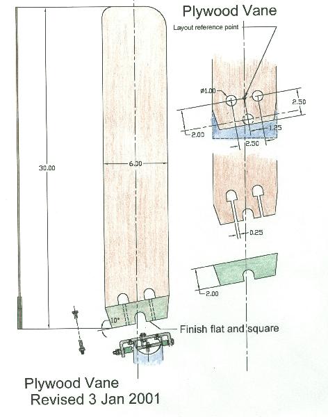
The vane is approximately 6 by 30 inches with two cheek pieces glued to the bottom end to form a flat base to support the bolts securing it to the aluminum bar of the carrier assembly. If you are looking for light air capability or if the friction in your linkage is higher than the design then you might want to make the vane larger. The sketch above is
how two builders made theirs.
The 10 degree base cut will cause the vane to tilt two degrees aft and put the center of pressure nearer the leading edge and help the vane feather into the wind. This assumes that the vane pivot axis is pitched or tilted up 12 degrees. This tilt angle is not very critical and 10 to 15 has worked fine for me.
However, an angle of 20 degrees will be better for stability and the difficulty of connecting the vane output crank can be
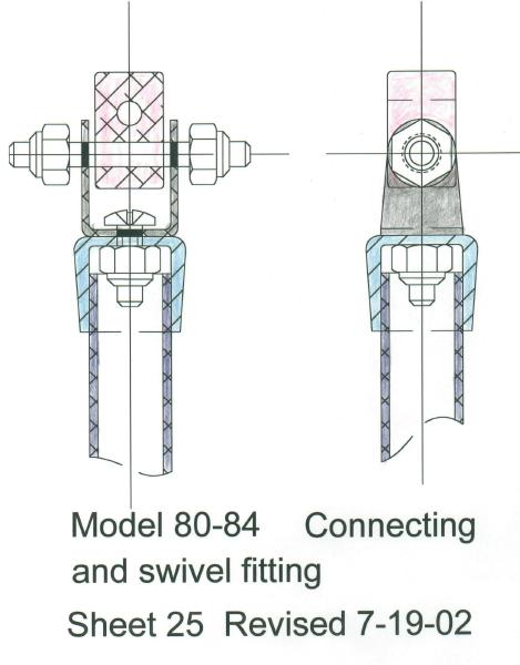
overcome with careful positioning of the push rod and the vane crank arm .2 - Vane Carrier
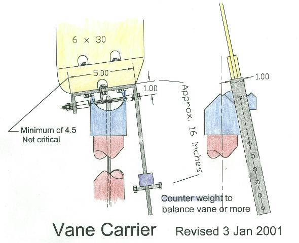
The vane carrier pivots on a 1/4 inch bolt or pin.
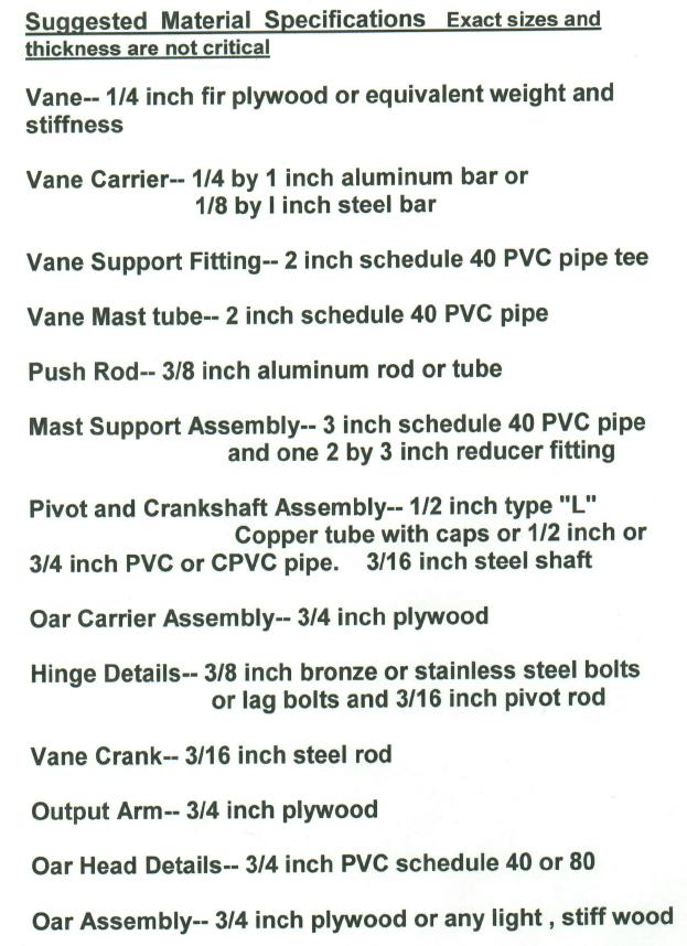
The bar is a 1x1/4 inch, soft aluminum or 1/8 steel and is bent to carry the lead counter weight of about two pounds. This weight is fitted to easily slide up or down on the bar to allow adjustment of the amount of counter weight torque needed for best performance depending on wind strength.
Normally a small amount of excess counter weight will help in most conditions.3 - Vane Support Fitting
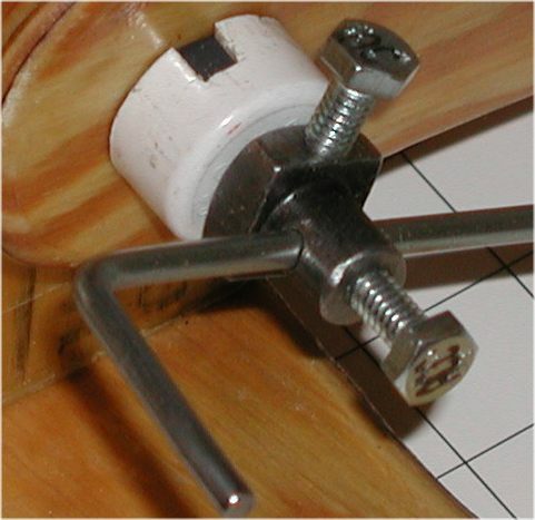
The vane support fitting is cut from a schedule 40 - 2 inch PVC pipe tee fitting and serves as a bearing for the pivot action of the vane. The material is easy to cut but is quite tough. The cuts are made to limit the swing to about 45 degrees either side of vertical.
Rough cut the part and drill for the shaft. Then install the carrier bar. This will indicate the additional material to be cut away to obtain the proper travel stops.
The drawing shows about a 10 -12 degree pitch up of the pivot axis. This is not critical and some designers don't think it worth while.
However, 20 degrees will provide better stability in the
operation of the gear but will also reduce some of it's power.
It becomes a choice for each boat to get the best compromise.
The heeling of the boat does provide some tilt to this axis. My feeling is that since it is so easy to do and even a little help with stable operation is good , why not? The related photos page has several photographs of this part to aid in cutting the part. It may look like a difficult part to make but once you start I think you will find it is rather easy. At the price of one of these fittings it is no problem if you don't get the first one just right.See photos 65 and 66 for results of a wear test conducted on
a PVC fitting to evaluate the wear to be expected. Both the
bearing load and the number of cycles indicate that wear will not be a problem.4 - Vane Mast Tube
The mast is just a length of 2 inch schedule 40 PVC pipe. It can be made in sections by using coupling fittings and that would allow easy breakdown of the gear for storage. The over all length will be determined by the size of the boat and rail configuration.7 Push Rod and Fitting
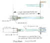
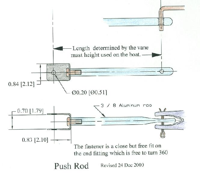
The push rod shown in the drawings is made from a 3/8 inch aluminum rod. This is over doing it but should be easy to find. Any stiff and light material could be used and an aluminum tube would be fine.A clever design for the swivel and push rod
was suggested by Paul VandenBosch
The plastic tube end cap is drilled for a loose fit and the stainless screw and lock nut is adjusted for
minimum backlash or play before the tube is
attached. A small sheet metal screw could be used
to secure the cap to rod and allow for accurate
adjustment of the rod length before final assembly.
This is my adaptation of his idea.
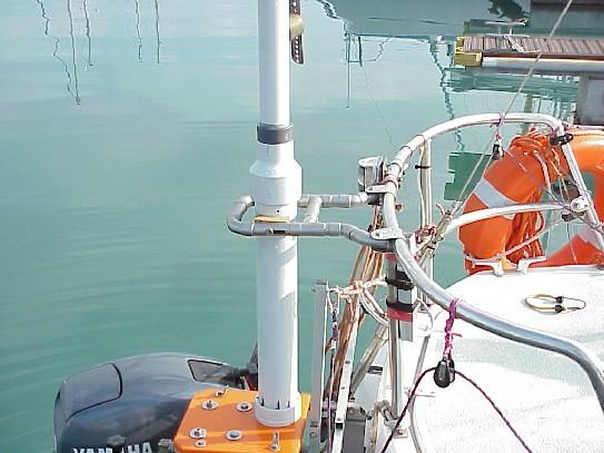
5 - Mast Support Assembly
The mast support assumes a free standing mast but if a stern rail is installed it would provide a good place for a brace or two. The length of the 3 inch tube could be increased to allow the course setting line to exit near the deck level.
An example of such a brace is shown in this photo.

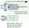
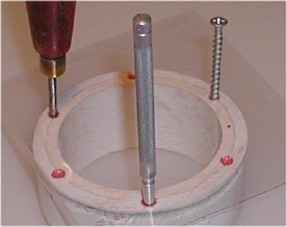
An alignment jig made from a clear plastic sheet such as
a blister pack container can be helpful in drilling the holes
for the PCV to plywood attachment. First drill the PVC and
use a punch through the plastic to transfer the pattern to the platform.
Be careful to turn the proper side up for this match.
Photo set up to show the alignment tool.
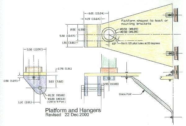
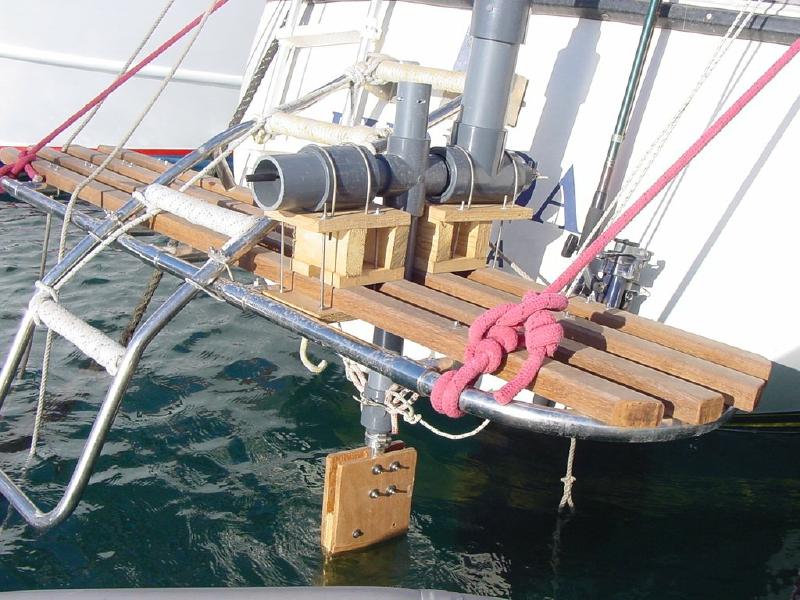
6 - Platform
The platform is made of 3/4 inch or thicker plywood and can be cut to any shape to conform to the boat's configuration. The only dimension that is important is the offset of the push rod to the "crooked" crankshaft.
My personal preference would be to combine the plywood
and copper tube idea as shown on the " Advanced " page and Photo " Gianello-21 "See photos 61 and 62 for a different approach for the
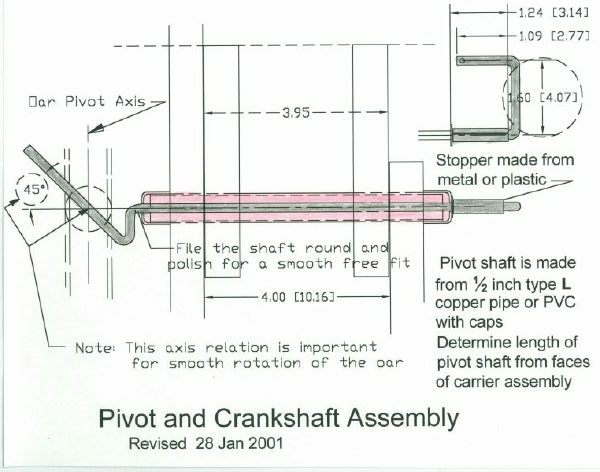
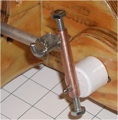
pivot shaft carriers.8 - Pivot and Crankshaft Assembly
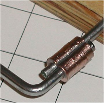
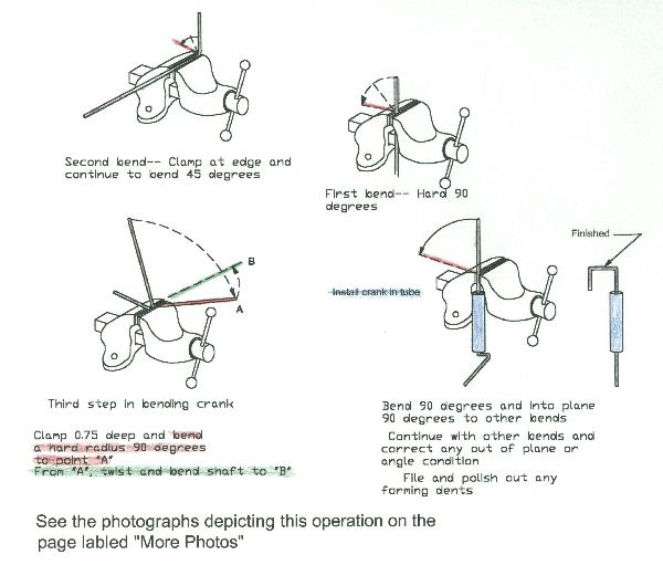
The oar carrier rotates about this shaft and the input "crooked" shaft is concentric with and in turn rotates inside this outer pipe. The bent rod shaft is shown with the out put end bent up 45 degrees. A smaller angle will result in less oar rotation with the same vane travel. If a smaller bend is tried adjust the bend so the axis relationship of the three axis remains the same.
A one half inch, heavy wall PVC pipe and caps can be substituted for the copper pipe shown and will be quite adequate.A difficult problem for several builders has been the bending of the crankshaft 90 degree bends after the pivot shaft has been inserted through the hangers and the output arm holes. I suggest that the first trial assembly of these parts be made with the pivot shaft before the crankshaft is installed. This will allow fitting all these parts and making any corrections that might be needed. Disassemble the parts and them add the crankshaft. Sliding all the hanger parts to one end will help provide working room to make the final bends.
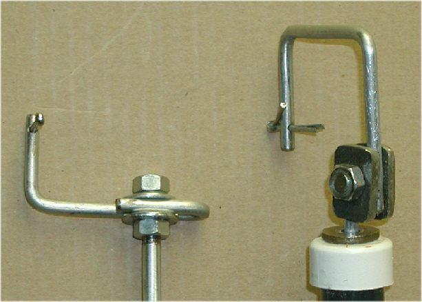
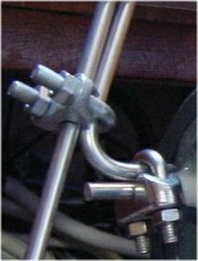
Alternate solution to this problem might be to make a coupling to clamp on the crank arm. Several ways to make such a coupling are shown in photos 60 67 68 and 69. Of course welding would do the job.
Clamps or threaded rod #60
Made from a bolt head #67
Swaged cable fitting #68
Bronze rod drilled and tapped
Photo #69
This shows stainless cable or wire clamps that allow for easy adjustments.
Photo #71
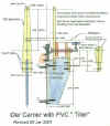
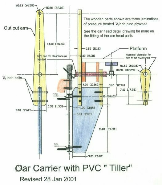
9 - Oar Carrier Assembly ( with PVC Tiller )
See 17 on JPG page for alternate tiller arrangements
" More Photos " 47, 48 show more details.
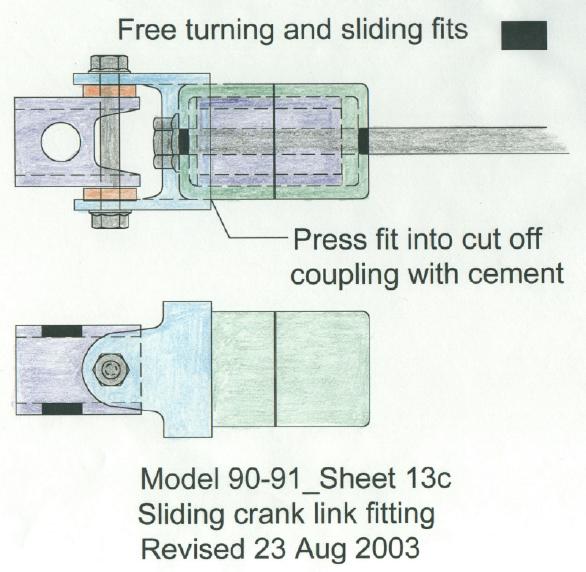
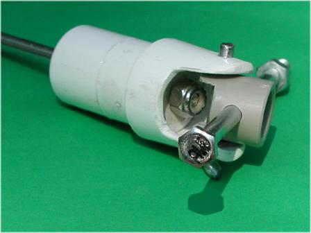
This sliding fitting is made from 3/4 and 1/2 inch PVC
fittings to connect oar tiller. Build with a minimum of
play between parts to avoid backlash in the action
but with smoothly sliding and rotating joints.
It is also an alternative to the pair of sliding Teflon blocks or the fitting shown in 48
These are nominal 3/4 inch plywood parts to be
initially fastened with 2 inch drywall screws and later bonded with epoxy after all parts are fitted and after a trial sail. The screws alone are adequate for strength but the epoxy will also waterproof the open grain of the wood.
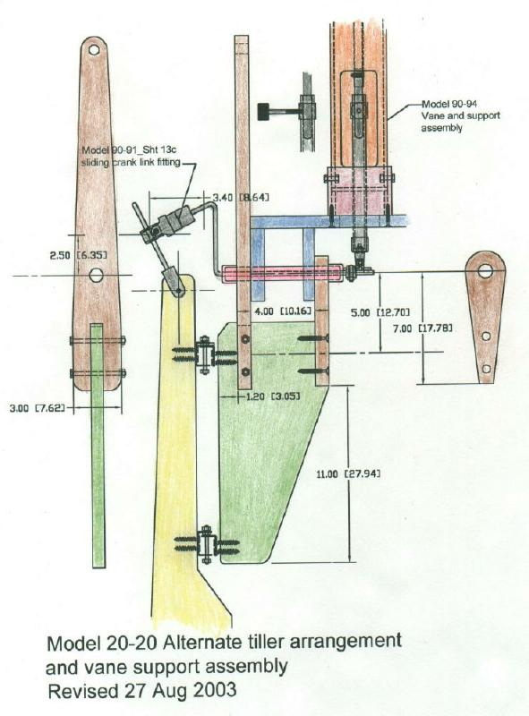
The output arm could be eliminated by attaching the output lines to the bottom of the oar carrier and crossing them to connect to the boat's tiller. This would be required to get the proper sense of the oar movement to the rudder movement.9B -Alternate tiller and vane support assembly
This later design has several features that have been used by builders and is my preferred
arrangement.9C - Another completely different oar carrier
A satisfactory one using two inch pipe and a more basic
layout is shown in the photo " CB " . Model 2004 on the
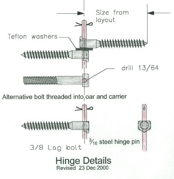
advanced page is what I see as a evolution of this part.10 - Hinge Details
The lag bolt hinges are simple and easy to fabricate. The screws allows for adjustment and if made of bronze or stainless and a stainless steel pin it will be very corrosion resistant. Over size the holes to get a smooth action and correct any little misalignment with the carrier and oar. Twisting one screw a little will aid in inserting the hinge rod. Twist it back for a good fit and alignment.
Machine bolts threaded into the wood may be substituted for the lag bolts.Several builders have used just simple angle brackets as hinges and found them satisfactory.
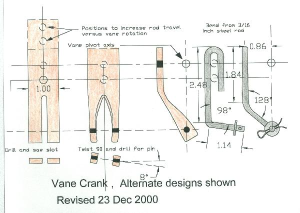
11 - Vane Crank
Form this from a 3/16 inch rod and clamp to the vane carrier bar with a 1/4 inch bolt. Adjust to get a free movement of the push rod and out from the pivot shaft the same distance as the off set on the "Crooked" crankshaft at the lower end of the push rod. The bar stock version is an alternate way to build it.12 - Out put Arm See Oar Carrier Assembly Drawing # 9
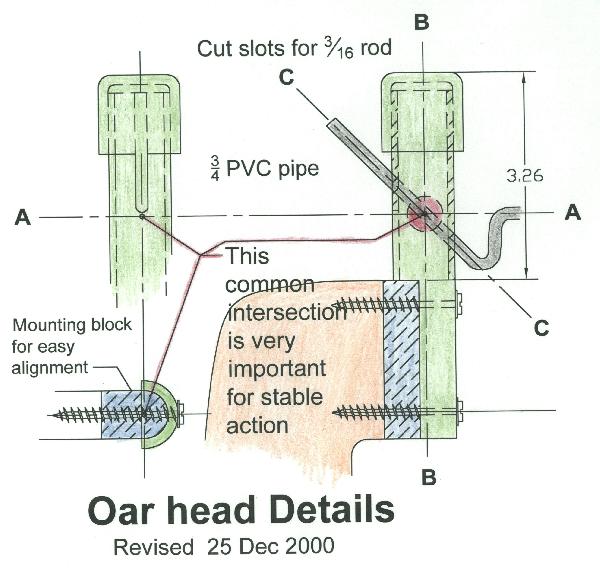
This version uses the output arm above the platform rather than using spreaders below it. Either scheme will work as well as the other. The routing of the output lines maybe better on one boat than another. The choice is yours.13 - Oar Head Details
The intersection of the three axis in this drawing shows a very important detail of this design.
These axes intersecting as shown is necessary for proper operation. The over all philosophy of this design is that it be simple to build but don't think it can be just thrown together and expect the best results. The linkage alignment and fits should be made so that there is no binding or hard to turn spots. If there are any they should be corrected. The crankshaft working in the oar head slot is
critical for proper operation. Make sure that it's horizontal axis and the oar's vertical axis coincide as shown.
Misalignment can be corrected by running the lag screw hinges fore or aft.
The alternate crank to an oar tiller
version will give the same performance
and may be easier for some to build.
Rather than the PVC pipe ,a simple hardwood
block will work well. Soak it in oil and fit as the PVC
one relative to the three axis caution statements.14 - Oar Assembly
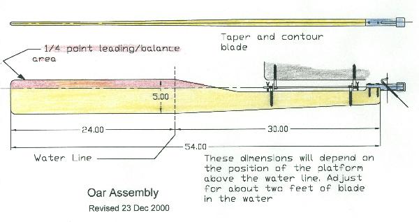
Make the oar from any stiff light wood or
laminated from plywood. Contour the blade to a thin airfoil profile with about two feet of the blade to be below the static waterline. A heavy blade may require a counterbalance to prevent gravity turning it the wrong way as the boat heels or pitches. There is room to attach a balance horn below the lower end of the carrier and above the water line. A kick- up or break- away blade may be added.18 - Bending Crankshaft Rod
These bends can be made cold in Brass or annealed stainless steel.
I have added a series of photos
on the "More Photos" page to help explain my
my method of bending the crankshaft.
These specifications are only suggestions in keeping with the philosophy of the design. Simple, easy to obtain materials. Substitutions can be made for almost any component and higher quality materials will result in a better product if the basic geometry is not altered and friction is kept low.
Additional Ideas and Thoughts
These are intended to be ideas of how to solve various problems related to building and using all self-steering devices.
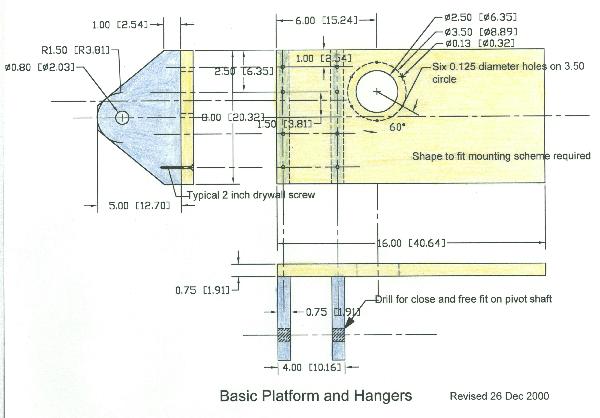
21 - Basic Platform and Hangers--an alternate design for simple construction
This basic platform can be modified to fit any mounting arrangement. By widening it and providing clearance for an outboard rudder head will make an easy way to fit to the deck and straddle the rudder.
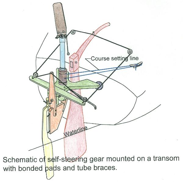
24 - Schematic of a typical mounting
25 - How several builders did their mounts

June 2001 issue
This one folds up and has Upside-
down wind vane and PVC oar carrier
Off set and direct connection to rudder
A version that was inspired by this site and built with PVC to prove the idea for a stainless
steel upgrade.See NOTES for more thoughts on building this
Basic 20-20 model


